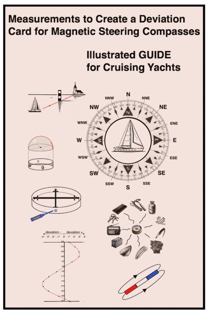
This guide explains how to create a marine magnetic compass deviation card, why it is essential for compass correction, and how it allows the construction of a compass deviation curve on board sailing vessels.
You’ll find the PDF guide with three different illustrated methods at the bottom of this page.

Furthermore, each vessel heading is associated with a specific deviation resulting from the interaction between the ship’s inherent magnetism and the Earth’s magnetic field.
In addition, to adjust a magnetic compass, you correct errors (deviation) caused by the vessel’s metallic structures and electrical fields by adjusting the corrector magnets.

By contrast, you create a deviation card by measuring the residual compass errors.
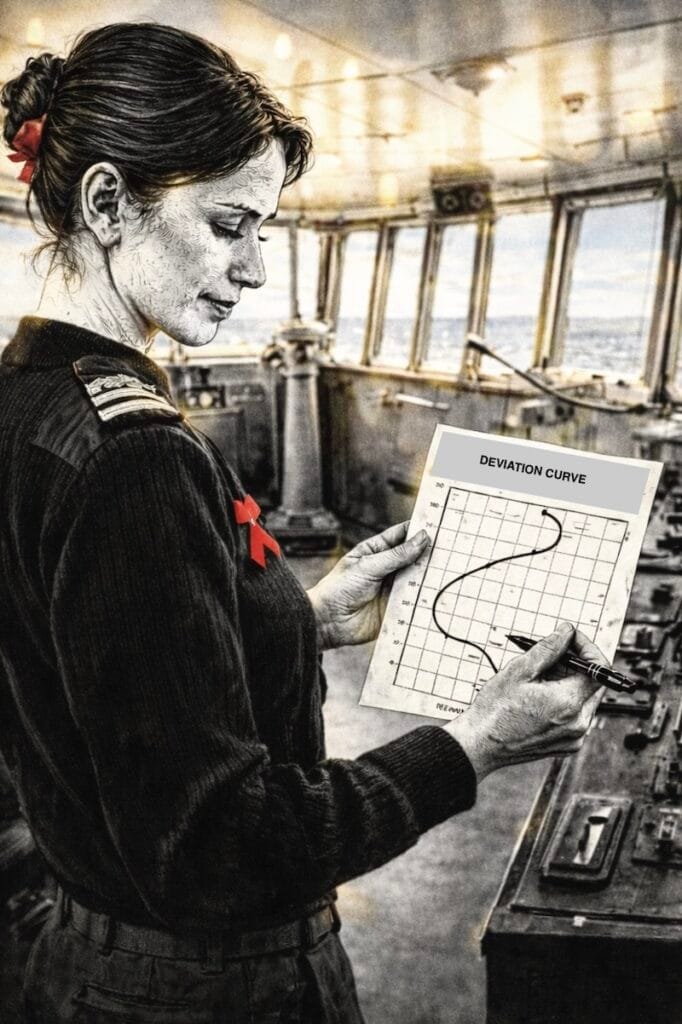
Next, the navigator uses this table to correct the compass course and, together with the magnetic variation, to determine the true heading.
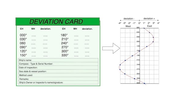
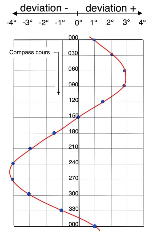
In general, deviation curves are plotted based on compass headings. However, when significant discrepancies are present, it is preferable to also plot them based on magnetic headings.
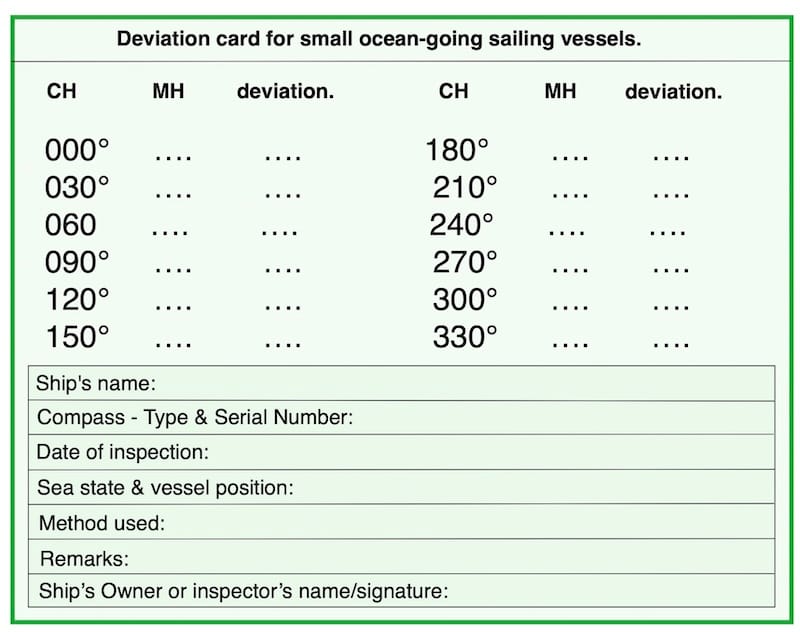
Alternatively, a simple table listing the deviations—along with the corresponding compass and magnetic headings—can be used instead of the curves.

Equipment for Magnetic Compass Adjustment and Deviation Card Creation
The bearing compass
The bearing compass shows no deviation when you place it well away from metallic or electrical disturbances.

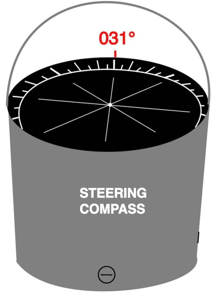
The steering compass
In contrast, the steering compass is affected by deviation due to its installation near such sources of interference.
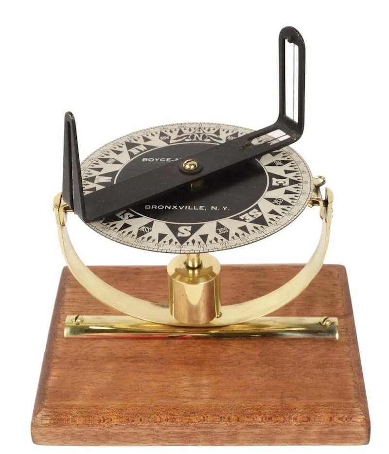
The pelorus
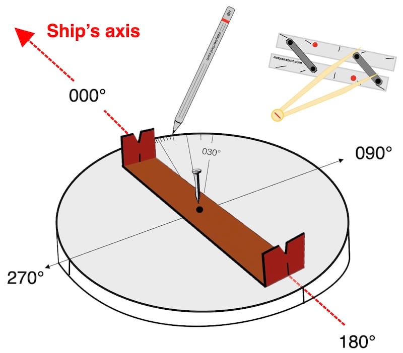
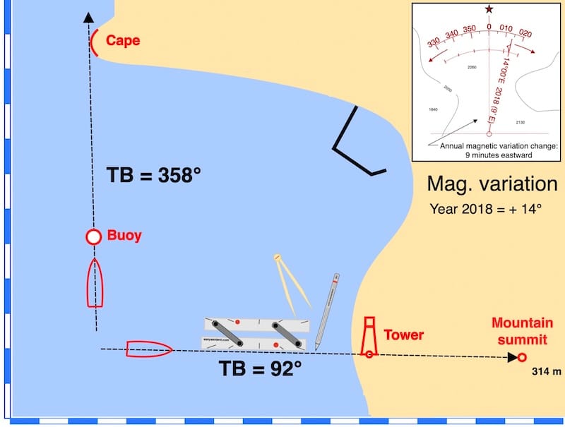
Firstly, one of the three recommended methods for creating a deviation card (or curve) involves the use of the pelorus.
a nautical chart with alignments
Creating a deviation card or a deviation curve is certainly easier than performing a compass adjustment.
Although similar to adjustment, this process tolerates more motion because it only requires taking compass readings.
Three Methods for Creating a Deviation Card
In general, the best spot for the hand-bearing compass is often at the stern when creating the deviation card.
For instance, the helmsman follows predetermined headings using the steering compass — 0°, 30°, 60°, etc.
Then, after stabilizing the heading, the magnetic bearing shown by the hand-bearing compass is measured and noted.
The main difficulty, however, is reading the hand-bearing compass precisely along or parallel to the vessel’s axis.
Finally, variation (Var.) has no impact on this method, as it affects both compasses equally.
Apart from working with a bearing compass in this guide, we will explore two additional methods to obtain the deviation curve.
Furthermore, each method is accompanied by fully worked-out examples and exercises.
Additional information
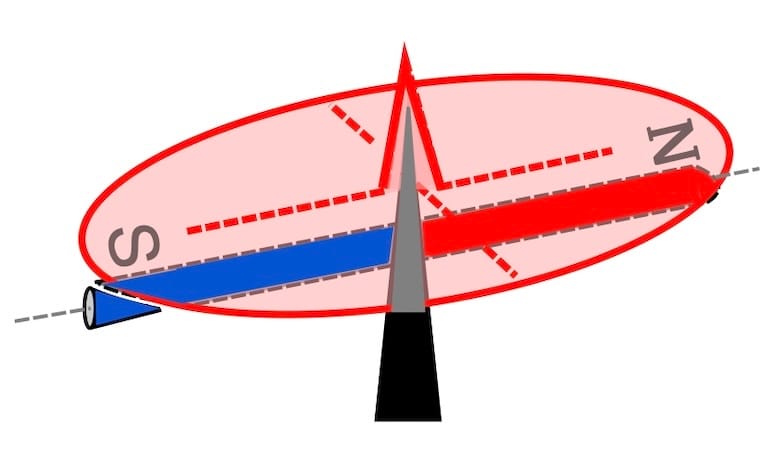
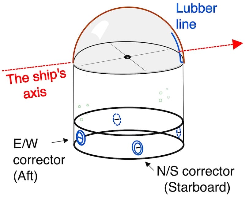
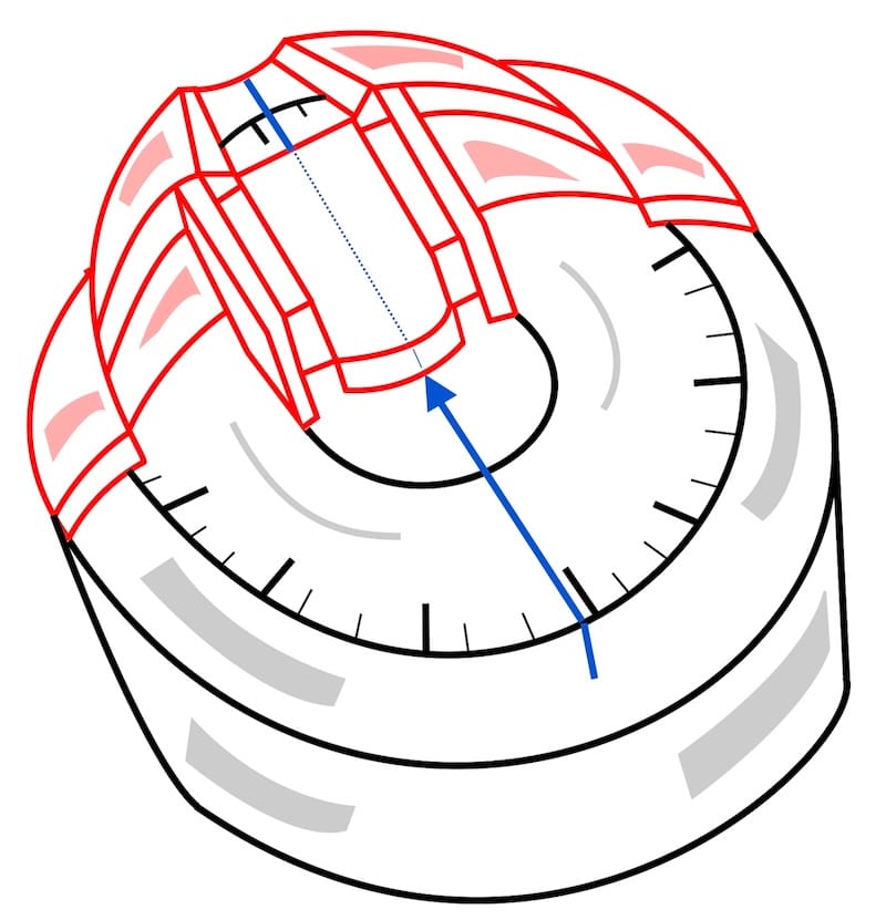
When the needle is mounted to the compass card, it holds steady with respect to the vessel. It is, in fact, the ship that swings beneath the card, giving the illusion of movement in the needle.
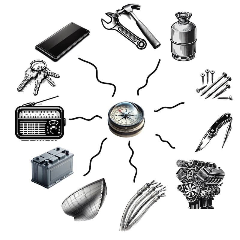
However, a single magnet (see illustration), symbolically representing machinery and electrical equipment, generates permanent magnetic fields that can interfere with the compass and cause deviation. Furthermore, if the hull is made of steel, significant deviations are to be expected
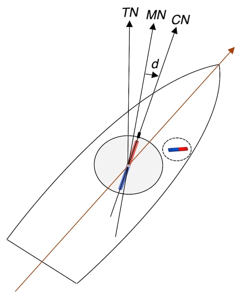

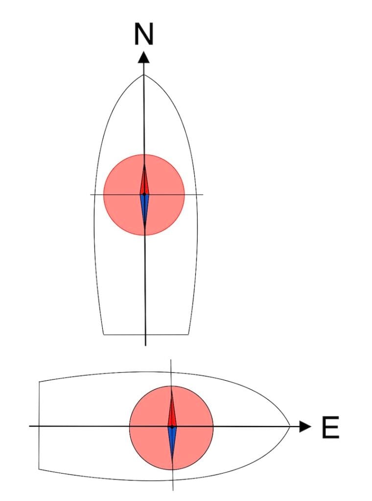
This deviation varies according to the ship’s heading, as it results from the vector sum of the Earth’s magnetic field and the permanent magnetic fields aboard.
Content of this PDF. GUIDE
Creating Deviation Cards (or Deviation Curves)
A.1 Creating a Deviation Card by Taking Simultaneous Readings from the Bearing Compass and the Steering Compass at Heading Intervals of 10°, 15°, 20°, 22.5°, or 30° (as per your choice). P
A.2 Creating a Deviation Card Using a Pelorus by Crossing a Known Alignment at Compass Headings Spaced 10°, 15°, 20°, 22.5°, or 30° — your choice — as Indicated by the Steering Compass. P
A.3 Creating a Deviation Card by Comparing the Steering Compass with the GPS Course at Compass Headings Spaced 10°, 15°, 20°, 22.5°, or 30° — your choice — as Indicated by the Steering Compass. P